Chris Collier
Microfluidic Glass-Elastomer
Membrane (GEM) Oxygenator
A flat-plate microfluidic oxygenator using a PDMS-coated glass membrane for blood gas exchange. Assisted with flow cell design in OnShape, assembly protocol development for consistent channel heights, manifold design and sealing iterations for multi-channel scaling, and a structured V&V testing framework for leak detection, dye perfusion, and pressure hold testing.
Extracorporeal Membrane Oxygenation (ECMO) is an advanced therapy for cardiac and respiratory support that mimics alveolar gas exchange outside the body. Current commercial oxygenators carry significant limitations such as large priming volumes, increased anticoagulation requirements, and uncontrolled internal flow patterns that can lead to hemolysis. These issues are seen in pediatric and neonatal populations, where device size and blood-contacting surface area must be minimized.
Prior lab work developed a silicon PDMS flat-plate oxygenator, but was limited to channel heights of ~500 µm due to 3D printing constraints and failed sealing above 15 psi. The GEM Oxygenator addresses both limitations: replacing the silicon PDMS membrane substrate with a glass slide produces a thinner, more dimensionally stable membrane, and a new polycarbonate flow cell with a mechanically fastened assembly achieves reliable, reproducible sealing. The ultimate goal is a reproducible 32-channel blood distribution device for clinical-scale gas exchange.
My work spans the full development cycle. CAD modeling in OnShape, fabrication and assembly, channel height validation, manifold design and sealing iteration, and a structured V&V testing framework to validate device compliance before advancing to biological testing.
Design & Development
01 — Flow Cell Design & Sealing
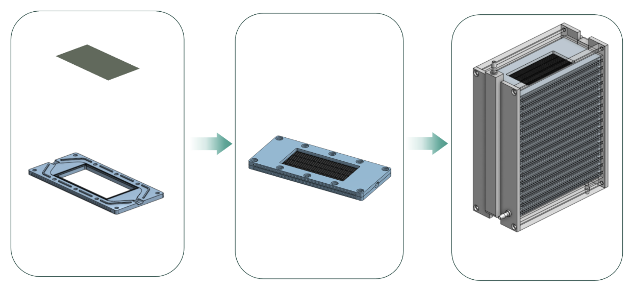
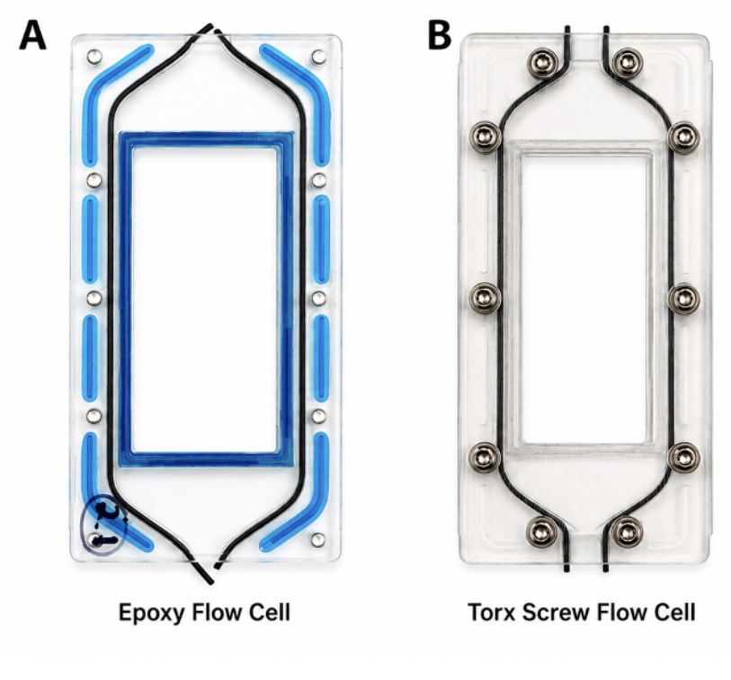
The polycarbonate flow cell was modeled in OnShape, defining blood channel geometry, gasket seating surfaces, and the fastener pattern. Viton cord stock serves a dual purpose, setting channel height while acting as the compression seal. Two assembly methods were evaluated: 302-3M epoxy with C-clamps, and eight Torx screws driven to a set torque. The screw design proved superior, removing adhesive cure variability and making channel height a direct function of applied torque.
02 — PDMS Membrane Fabrication
The gas transfer membrane is a thin PDMS film spin coated onto a glass slide, where spin speed sets film thickness. PDMS provides high permeability for O₂ and CO₂ transfer while remaining biocompatible. The glass backing replaces the previous silicon substrate, producing a thinner and more dimensionally stable membrane while providing a flat, rigid bonding surface for assembly into the flow cell.
03 — Channel Height Refinement
Channel height drives flow resistance, residence time, and gas transfer efficiency. It was verified two ways: micrometer measurement of assembled devices and CT scanning of the internal blood channel. Results confirmed that applied torque directly determines height. At 80 cN·m, devices consistently landed in the 125–175 µm target window, while over-torquing to 100 cN·m collapsed the channel to 70 µm, making assembly protocol compliance critical to reproducibility.

04 — Manifold Design & Sealing
Scaling to a 32-channel system requires a blood distribution manifold that connects to the flow cell ports and feeds every channel in parallel. The manifold was designed in OnShape and printed on a Formlabs resin printer for dimensional accuracy. Three sealing iterations were tested: an unsealed baseline, adhesive grooves, and the current grooves with O-ring face seal, sized per the Parker O-Ring Handbook using measured stretch fit.
05 — Verification & Validation Testing
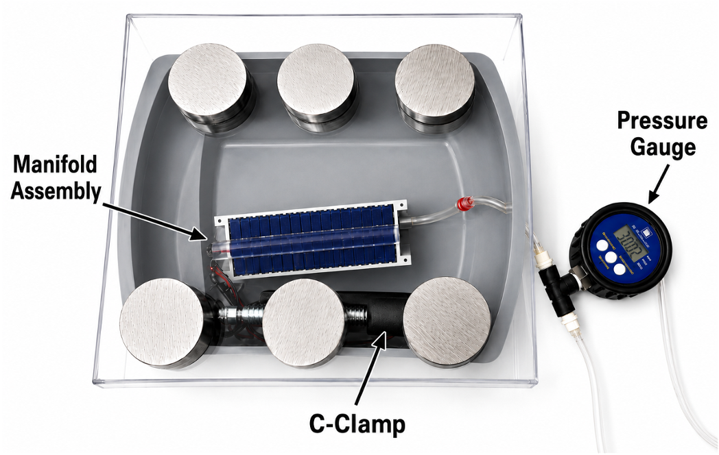
A structured V&V protocol characterizes device integrity at each stage of development. External leak testing combines a pressure hold protocol with a submersion test to visually locate leak paths. Flow cell integrity is confirmed by dye perfusion, verifying that flow stays within its channel. The manifold assembly is pressure hold tested in psi and compared against physiologic blood pressure in mmHg to confirm sealing under expected loading.